Dealing with the encoders, theoretically
Failure to encode
Tragically, we have hit a speed-bump with the project, the phototransistor on one of the encoders is dead. Obviously this calls for a moment of silence.
The rest of the circuit appears to be working fine, however. While I did want to implement the code to utilise the encoders, it was never actually needed in order to get the robot to follow a line. I could probably replace the part and get it working again, but I do not feel it is worth the effort given the scope of the project. Despite this, my decision to not implement the encoder nodes isn’t a total loss. I did write a simple callback function to test, and did a bit of digging into the ins and outs on what we expect to be reading from the circuit. Following in the spirit of the first post in the QUAIL saga (Installing ROS2 on the raspi), I’m more interested in this series being informative than anything else, which means you’re going to learn about these encoders regardless. Let’s get into it.
Decoding the encoders
The Arexx website conveniently still hosts the datasheets for the RP6, including schematics. From the website we can download the RP6_schematics.zip, which contains some circuit diagrams for the encoder PCBs. The curcuit for the encoder looks like so:

Alright, so what are we looking at here? Well, I think most of the interesting behaviour is defined by three components:
- The Phototransistor (SFH-9202)
- The Op-amp (MCP6001U)
- The preset potentiometer R2 (200k$\Omega$)
Starting from the top, we have the SFH-9202. A quick online search leads us to the Datasheet, which lets us know that this IC is the Phototransistor that ‘reads’ the the black and white stripes on the gear. Incidentally, this is also the part that has failed on one of my encoder boards. Equipped with the datasheet, we can figure out how this transistor is being used. Pins 3 and 6 (Emitter and Cathode) are tied directly to ground. Pin 1 (Anode) is in series with a 680$\Omega$ resistor, which itself is tied to the 5V input. Pin 4 (Collector) is where things get a bit interesting, it ties to a 3 other lines:
- R2 in series with R3, which is used as a pull-up resistor allowing us to set the reference voltage of the signal into the Op-Amp, and therefore the sensitivity.
- The non-inverting input of the Op-amp.
- To a series resistor/capacitor, then to ground.
In order to visualise this better, I attempted to re-created the file in Falstad. I have very little faith that this is correct, but it seems to behave as I would expect. You can play with the circuit yourself here, if you spot anything wrong, please get in contact, I’ll make sure my customer relations team will take action within 3-5 business days.
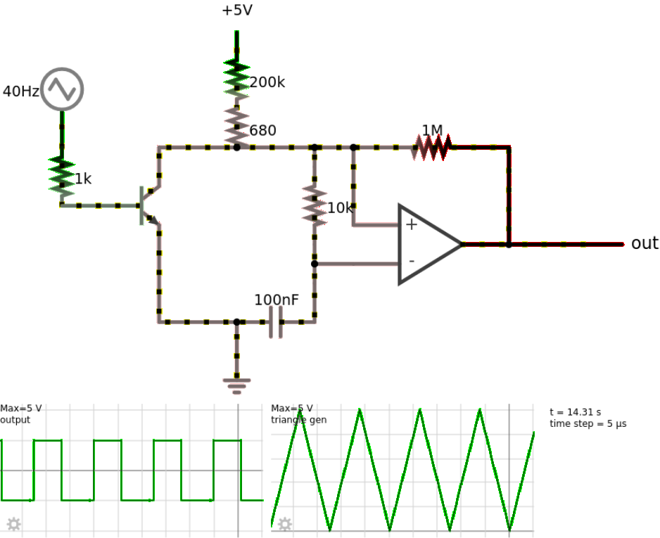
So, we can expect the ’ticks’ to range from 0-5V from the encoder. The particularly astute readers will realise we have a problem, and it can be found right here. Our GPIO inputs into the pi are not 5V tolerant. This means we weill need to use a logic level converter to convert out signal from 5V to 3.3V in order to be useful. However, once we do that, our signal should easily read by the GPIO as a High/Low input, so we can move on from here.
Coding the encoders
Alright, let’s just pretend that both our encoders are working as intended, and we have everything wired up correctly (If you’re feeling extra daring, imagine that you wired it up correctly the first try). Now onto the fun part, writing the code to read the encoders. I stole most of this from the pigpio website, which lists a supposedly working program to read the inputs from an encoder here. You will want to grab the ‘Rotary Encoder’ file under the ‘pigpiod_if2 code’ section.
There are a number of differences between our use-cases, so a bit of sanding and duct-tape is required. If you are wanting write your own code to read the encoders, that link is what you will need. You will find everything you need in the example program, just make note of the fact that our encoder is single channel, while the example code has been written for a dual channel encoder.
I actually spent many hours trying to figure out a way to write about and document the code I had written to read from the encoders (I think more time than I actually spent writing the code). Unfortuanately, there simply wasn’t anything of interest, each attempt simply devolved into essentially ‘Here is the callback and here is how we define it’. Which, why bother doing that when I can just point you to the documentation for the callback we’re using. Don’t get me wrong, I’d love to waste your time, but I’d like to at least be novel about it, perhaps even entertaining.
And with that, I’m out of things to talk about. We will be moving on to light sensor bar next, and figuring out how best to interface to it.