The hardware of QUAIL
The chassis
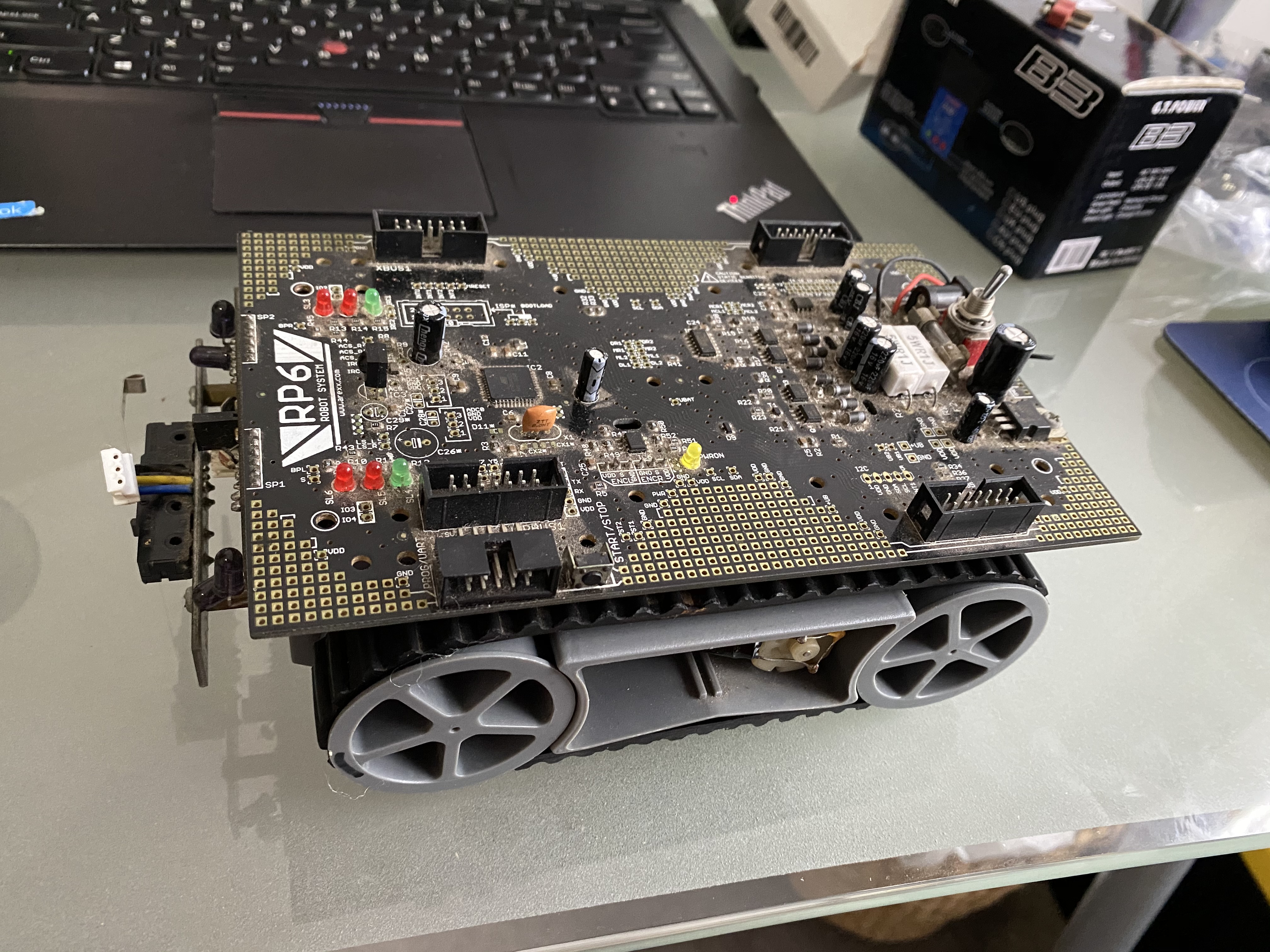
This is an Arexx RP6 robot platform. I have spent a lot of time messing with this thing over the years, and I have learned a lot from it. The website for it can be found here: RP6 Robot system (I highly recommend doing some browsing around their website, it’s a reminder of a time when websites had character). A run down of the specs lists an 8-bit ATMEGA32, a pair of optical encoders, motors, light sensors, touch sensors, the whole shebang. It’s definitely not the conventional platform for following a line, and it won’t be breaking any land speed records any time soon. That being said, there are a number of reasons why I think using this platform for QUAIL is a good choice:
- It’s right here, not being used, I may as well find a use for it.
- Writing some nodes to interface with the motors and encoders will allow anyone else who wants to use their RP6 with ROS to just use what I wrote.
- The ins and outs of controlling a tracked robot can be deceptively complicated, if you want it to move smoothly during complex manoeuvres. I want to see how well it can perform.
- As far as platforms go, it has a ton of potential for future projects, if I ever want to try my hand at something like SLAM.
The Motors
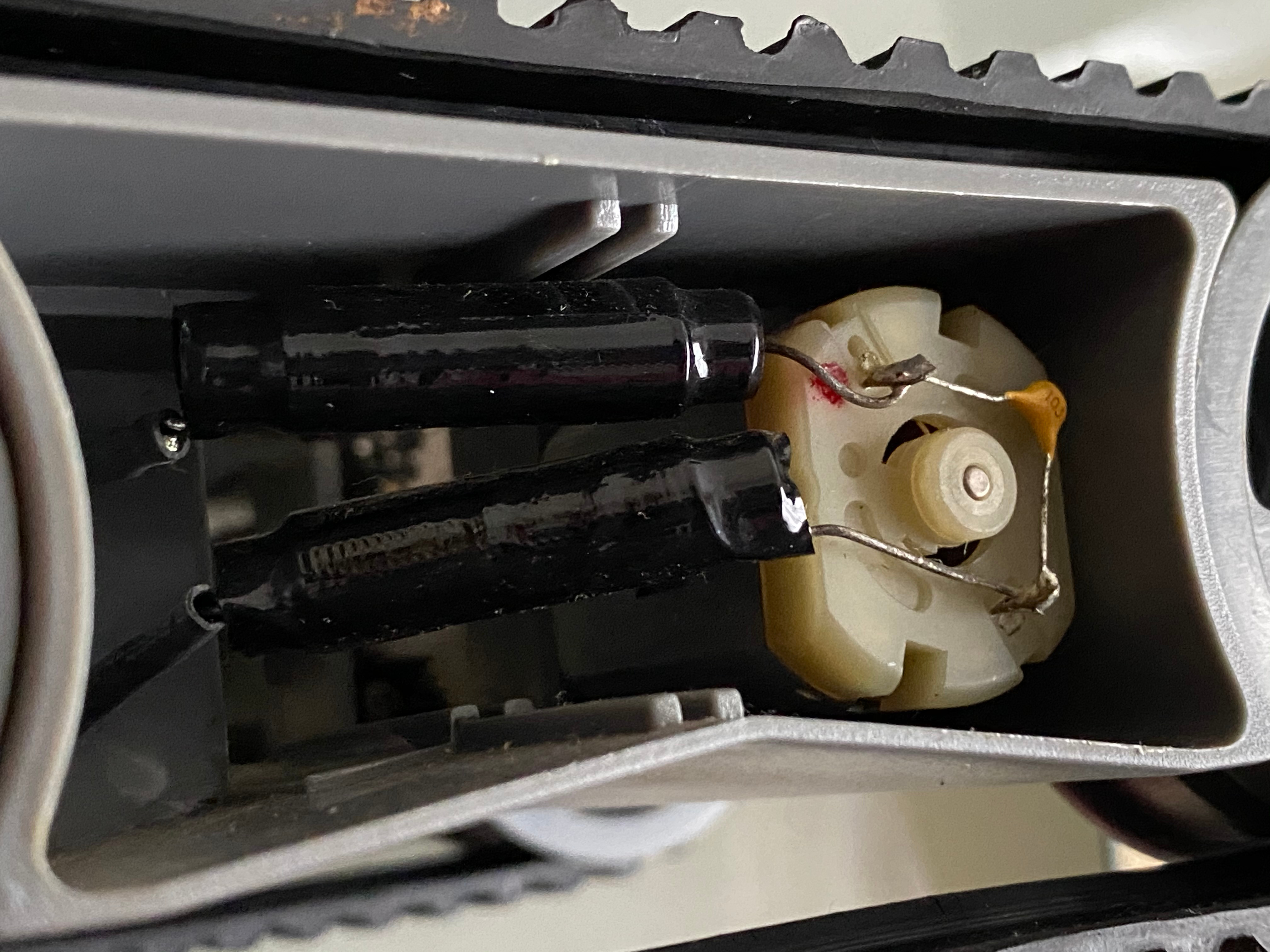
I Think these bad boys are TECO TFK280SC-21138-45’s, which according to the datasheet have a voltage range from 5 - 7.5V DC, which lines up nicely with our 2s Li-Po. We shall be using PWM to control the motor current, which is achieved through the L298N motor driver, which itself is a H-Bridge. This allows the Pi to ‘Toggle’ the line from the motor to the power source open and closed, without having to deliver the driving current itself. By changing the frequency of these toggles (Modulating the width, if you will) we can control the RMS current running through the motor, which how we shall control our power output.
The Encoders
The encoders on the RP6 are optical encoders, of the incremental kind, as opposed to absolute. This means that we can’t receive information about what angle the wheel is at, only how fast it is turning, which is still useful information.
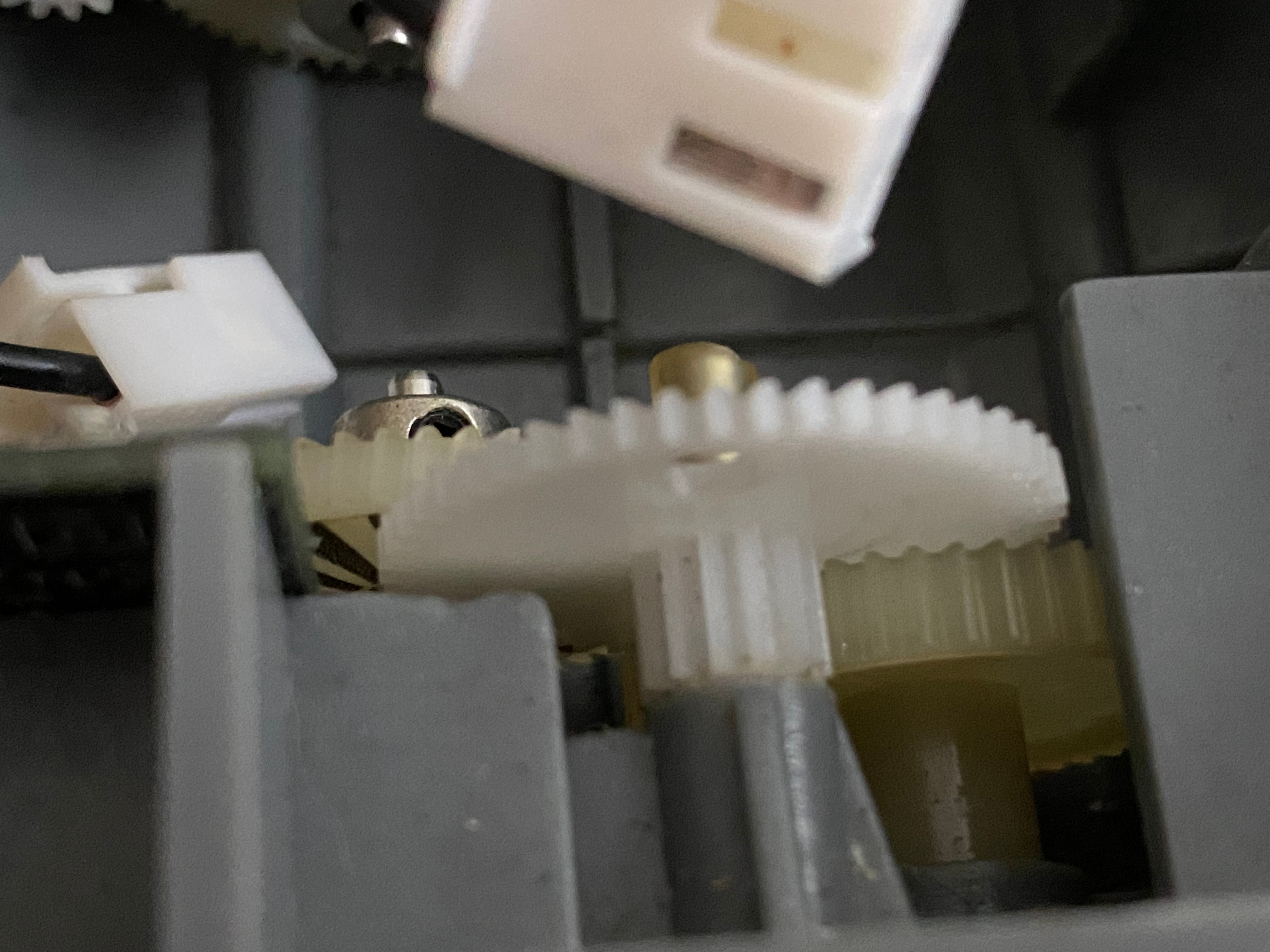
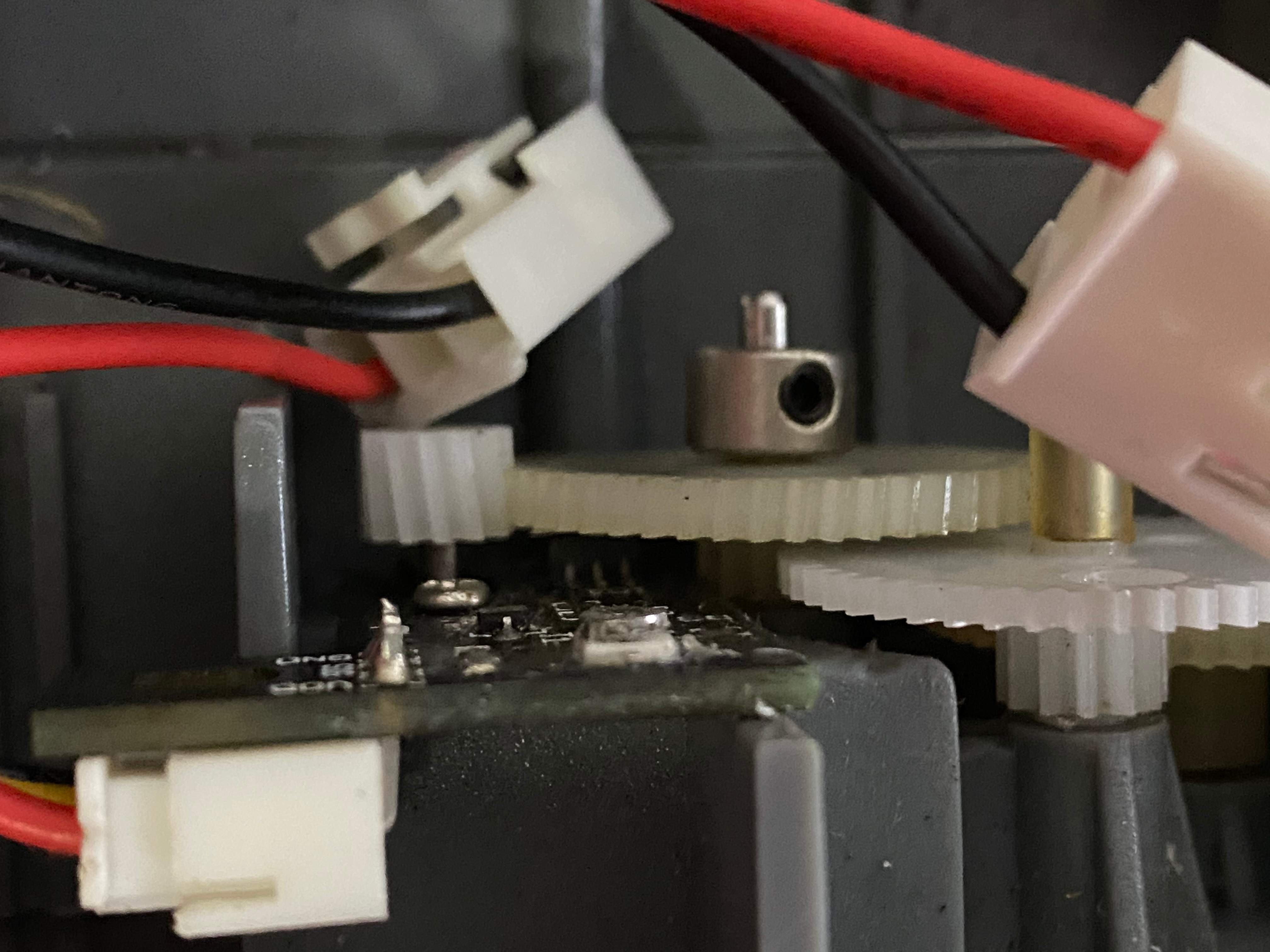
On the left, you can just make out the black stripes on the gear. These are picked up by an IR sensor, shown on the right. The mechanism behind this is almost identical to the sensor module we shall be using to allow the robot to detect the line. According the the manual, these have a resolution at 625 counts per revolution (cpm). This essentially means that for each $2\pi$ rotation of the wheel, we should count 625 ticks from the encoder. In theory this should give us an accurate enough measurement of how fast the wheels are rotating to drive straight. As for any kind of localisation, I’m skeptica l of how useful they will be.
The Equipment
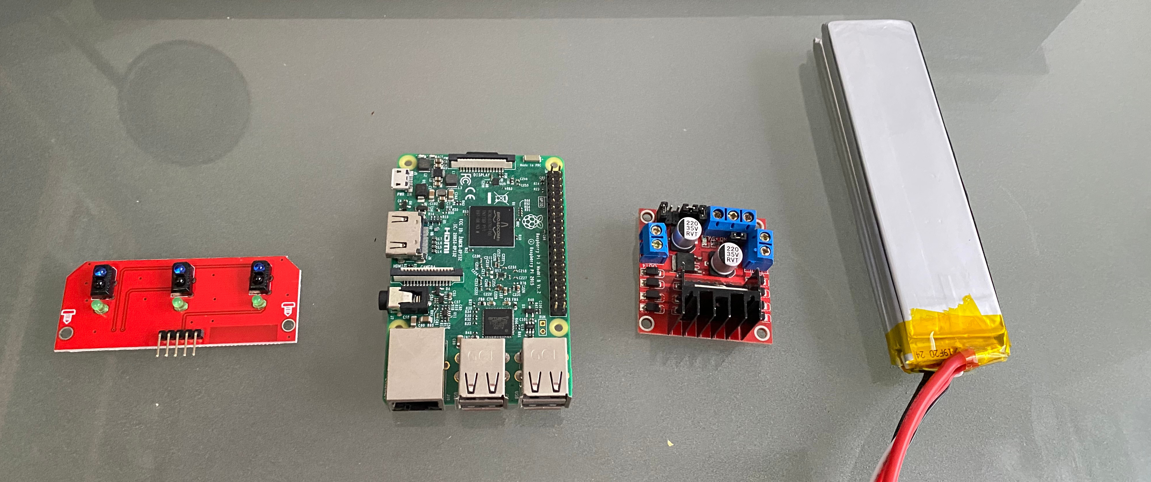
From Left to right, we have:
- Duinotech triple reflectance sensor module
- A raspberry Pi 3 B
- L298N motor driver, which will also serve as the voltage regulator for the to power the raspberry pi.
- 2s Li-Po battery.
I wasn’t interested in doing any circuit design, so I played it lazy and grabbed the sensor module for the lights and sensors to detect the line, as well as the tried and true L298N motor driver. From factory, the RP6 is designed to utilise 6 AA batteries, and obviously that would not do. Thankfully, the slot left in the chassis that was originally the housing for the batteries, is almost perfectly sized for the 2s Li-Po. Probably a coincidence, but given how well thought out the robot platform is as a whole, it would not surprise me if it was all part of the plan.
Putting it all together
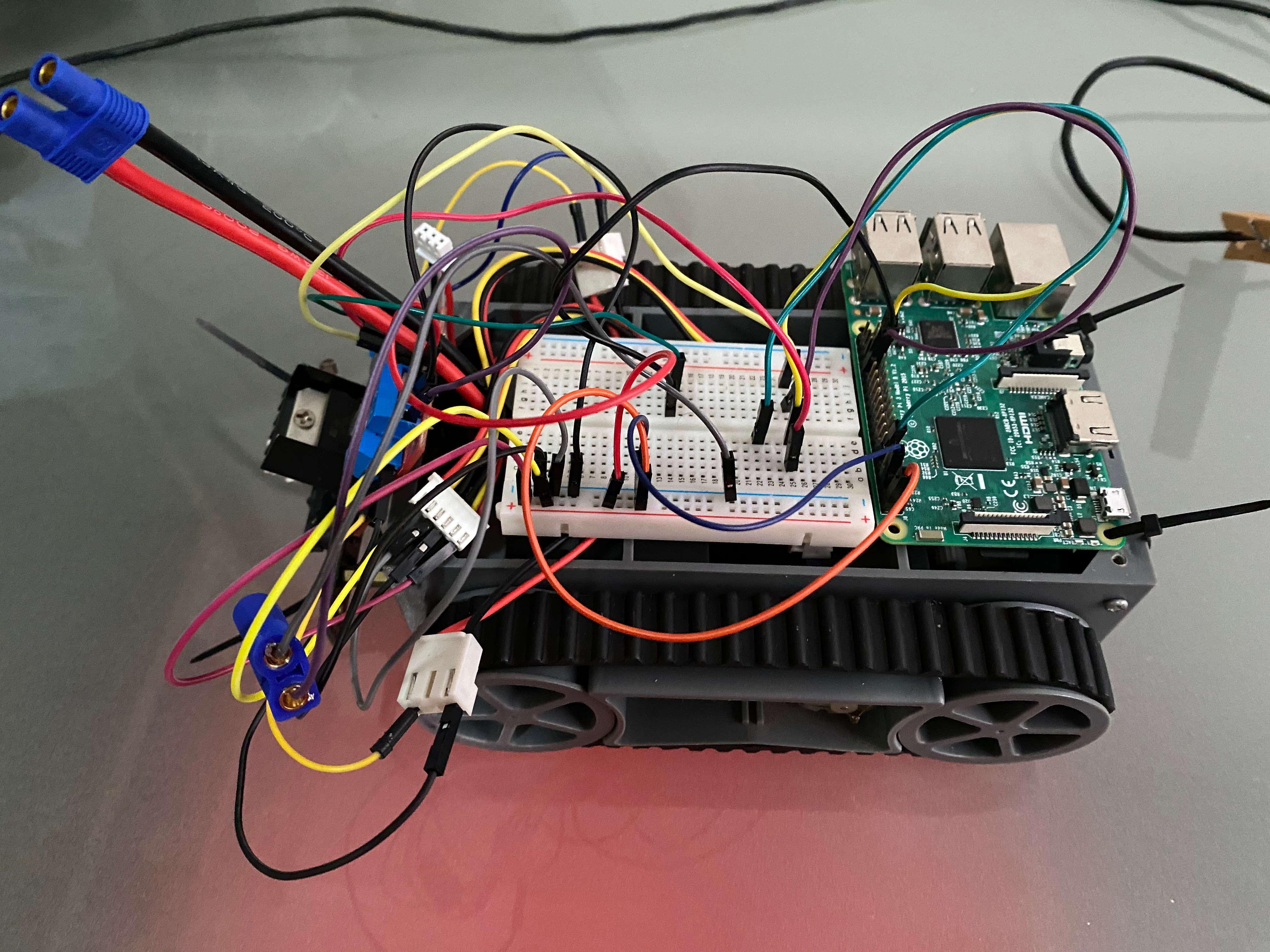
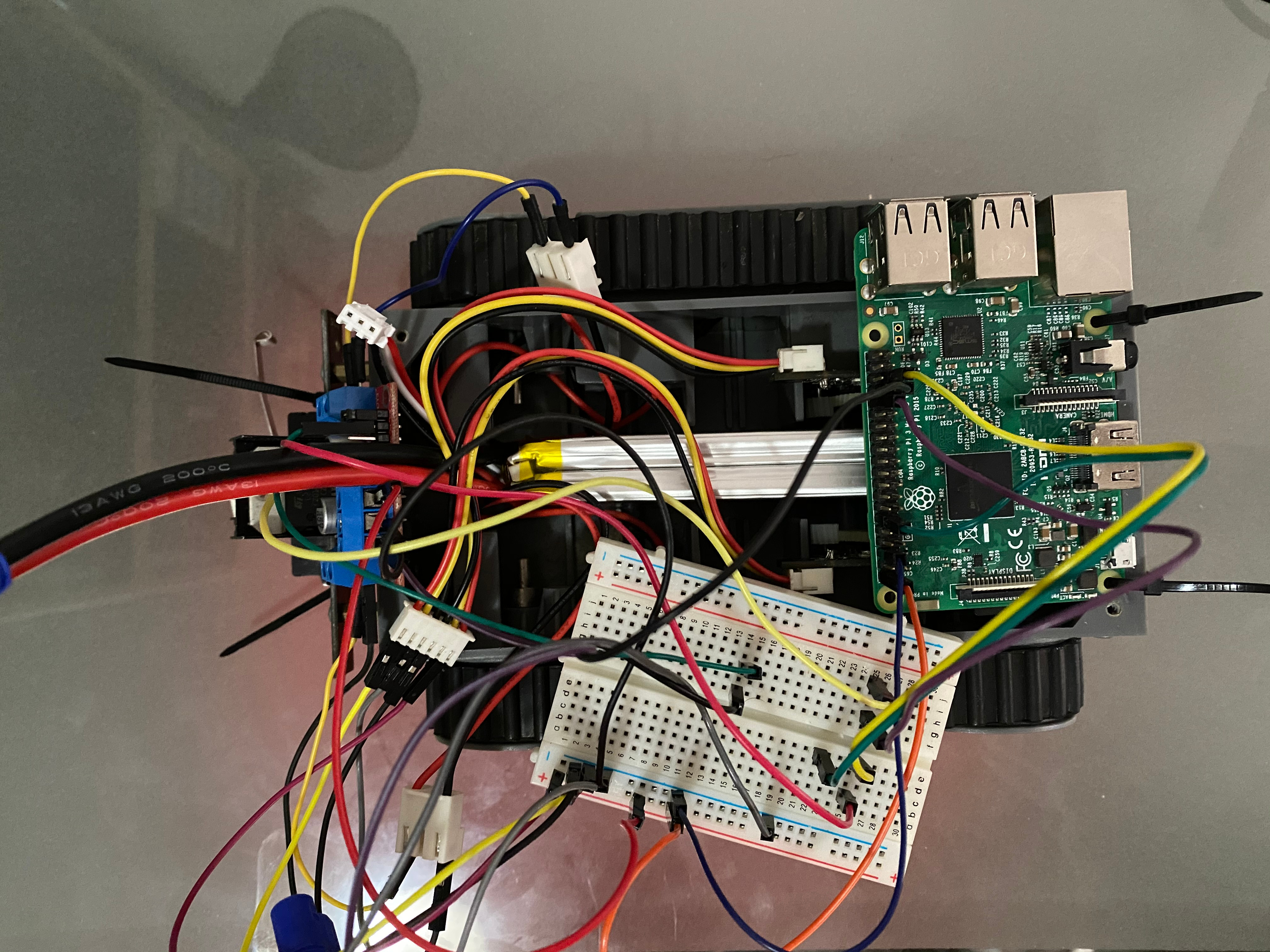
Yes, it is hideous. No, I’m not going to apologise. After a bit of poking with a multimeter, and giving it some power, both the motors and the encoders appear to still be working well. I also pulled apart the drive-train and gave it a clean/fresh coat of WD-40. When I get my life together I’ll re-make this with some vera-board and use actual plugs/connectors. Electronics has never been my strong suit, I tend to find that I spend more time dealing with the fact that I don’t have the parts I need than I do dealing with actual circuit issues. As a direct result of this, if you were to sum up my knowledge of electrical engineering, it would be as follows:
- If you arrange four Diodes into a diamond, you can rectify an AC source into DC.
- If you say the words ‘magic white smoke’ to an electrical engineer, they will laugh. Always. I don’t get it either.
And with that, there you have it, the BOM for the QUAIL. I have absolutely no doubts that I’m missing something, or that one of my components won’t work. For now though, this is what we’re working with. From here, we get into writing something to spin the tracks.